| Elements of Section – A1000 | ||
| Area of Section | 0.305 in2 (2.0 cm2) | |
| Axis 1-1 | Axis 2-2 | |
| Moment of Inertia (I) | 0.061 in4 (2.5 cm4) | 0.078 in4 (3.2 cm4) |
| Section Modulus (S) | 0.086 in3 (1.4 cm3) | 0.125 in3 (2.0 cm3) |
| Radius of Gyration (r) | 0.447 in (1.1 cm ) | 0.506 in (1.3 cm ) |
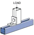
| Column Loading – A1000Unbraced Height (in)Allowable Load at Slot Face (lbs)Max Column Load Applied at C.G.K=0.65 (lbs)K=0.80 (lbs)K=1.0 (lbs)K=1.2 (lbs)181,9605,9005,4304,8004,210241,8405,2104,5903,8503,220361,5003,9403,2202,4802,010481,2202,9502,3001,7901,460601,0202,2601,7901,4001,130728801,8401,4601,130910847801,5501,230940*966901,3401,050**1086201,170910***KL/r > 200 |
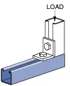
| Beam Loading – A1000 | ||||||
| Span (in) | Max Allowable Uniform Load (lbs) | Defl at Uniform load (in) | Uniform Loading at Deflection | Lateral Bracing Reduction Factor | ||
| Span /180 (lbs) | Span /240 (lbs) | Span /360 (lbs) | ||||
| 18 | 960 | 0.04 | 960 | 960 | 960 | 1.00 |
| 24 | 720 | 0.07 | 720 | 720 | 660 | 0.95 |
| 36 | 480 | 0.16 | 480 | 440 | 300 | 0.86 |
| 48 | 360 | 0.29 | 330 | 250 | 170 | 0.78 |
| 60 | 290 | 0.45 | 210 | 160 | 110 | 0.72 |
| 72 | 240 | 0.65 | 150 | 110 | 70 | 0.67 |
| 84 | 210 | 0.90 | 110 | 80 | 50 | 0.63 |
| 96 | 180 | 1.16 | 80 | 60 | 40 | 0.59 |
| 108 | 160 | 1.46 | 70 | 50 | 30 | 0.55 |
| 120 | 140 | 1.75 | 50 | 40 | 30 | 0.52 |
Notes:
- Above loads include the weight of the member. This weight must be deducted to arrive at the net allowable load the beam will support.
- Long span beams should be supported so as to prevent rotation and twist.
- Allowable uniformly distributed loads are listed for various simple spans, that is, a beam on two supports. If load is concentrated at the center of the span, multiply load from the table by 0.5 and corresponding deflection by 0.8.
- The lateral bracing factor should be multiplied by the load to determine the load retained based on the distance between lateral braces.