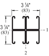
| Elements of Section – P1001C41 | ||
| Area of Section | 2.221 in2 (14.3 cm2) | |
| Axis 1-1 | Axis 2-2 | |
| Moment of Inertia (I) | 1.856 in4 (77.3 cm4) | 2.408 in4 (100.2 cm4) |
| Section Modulus (S) | 1.142 in3 (18.7 cm3) | 1.482 in3 (24.3 cm3) |
| Radius of Gyration (r) | 0.914 in(2.3 cm) | 1.041 in(2.6 cm) |
| Column Loading – P1001C41 Unbraced Height (in) Allowable Load at Slot Face (lbs) Max Column Load Applied at C.G. K=0.65 (lbs) K=0.80 (lbs) K=1.0 (lbs) K=1.2 (lbs) 24 12,690 46,920 44,980 42,360 39,890 36 12,250 42,680 39,890 36,660 34,050 48 11,820 38,740 35,720 32,640 30,430 60 11,470 35,500 32,640 29,980 28,220 72 11,180 32,970 30,430 28,220 26,820 84 10,900 31,040 28,840 27,010 24,870 96 10,580 29,570 27,680 26,170 19,840 108 10,310 28,440 26,820 22,310 15,670 120 10,070 27,560 26,170 18,280 12,700 144 8,740 26,320 19,840 12,700 8,820 168 7,360 21,890 14,570 9,330 * *KL/r > 200 |
| Beam Loading – P1001C41 | ||||||
| Span (in) | Max Allowable Uniform Load (lbs) | Defl at Uniform load (in) | Uniform Loading at Deflection | Lateral Bracing Reduction Factor | ||
| Span /180 (lbs) | Span /240 (lbs) | Span /360 (lbs) | ||||
| 24 | *7,040 | 0.02 | *7,040 | *7,040 | *7,040 | 1.00 |
| 36 | 6,380 | 0.07 | 6,380 | 6,380 | 6,380 | 1.00 |
| 48 | 4,790 | 0.13 | 4,790 | 4,790 | 4,790 | 1.00 |
| 60 | 3,830 | 0.20 | 3,830 | 3,830 | 3,240 | 1.00 |
| 72 | 3,190 | 0.28 | 3,190 | 3,190 | 2,250 | 0.98 |
| 84 | 2,740 | 0.39 | 2,740 | 2,480 | 1,660 | 0.95 |
| 96 | 2,390 | 0.50 | 2,390 | 1,900 | 1,270 | 0.93 |
| 108 | 2,130 | 0.64 | 2,000 | 1,500 | 1,000 | 0.90 |
| 120 | 1,910 | 0.78 | 1,620 | 1,220 | 810 | 0.87 |
| 144 | 1,600 | 1.14 | 1,130 | 840 | 560 | 0.82 |
| 168 | 1,370 | 1.55 | 830 | 620 | 410 | 0.77 |
| 192 | 1,200 | 2.02 | 630 | 480 | 320 | 0.72 |
| 216 | 1,060 | 2.54 | 500 | 380 | 250 | 0.67 |
| 240 | 960 | 3.16 | 410 | 300 | 200 | 0.62 |
| *Load limited by weld shear | ||||||
Notes:
- Above loads include the weight of the member. This weight must be deducted to arrive at the net allowable load the beam will support.
- Long span beams should be supported so as to prevent rotation and twist.
- Allowable uniformly distributed loads are listed for various simple spans, that is, a beam on two supports. If load is concentrated at the center of the span, multiply load from the table by 0.5 and corresponding deflection by 0.8.
- The lateral bracing factor should be multiplied by the load to determine the load retained based on the distance between lateral braces.