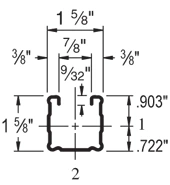
The P1100 is a 1-5/8″ x 1-5/8″ Unistrut channel. It is similar in size to the P1000, but with a 14 ga (.075″) wall.
| Elements of Section – P1100 | ||
| Area of Section | 0.418 in2 (2.7 cm2) | |
| Axis 1-1 | Axis 2-2 | |
| Moment of Inertia (I) | 0.145 in4 (6.0 cm4) | 0.176 in4 (7.3 cm4) |
| Section Modulus (S) | 0.162 in3 (2.7 cm3) | 0.217 in3 (3.6 cm3) |
| Radius of Gyration (r) | 0.589 in(1.5 cm) | 0.650 in(1.7 cm) |
| Column Loading – P1100 Unbraced Height(in) Allowable Load at Slot Face(lbs) Max Column Load Applied at C.G. K=0.65 (lbs) K=0.80 (lbs) K=1.0 (lbs) K=1.2 (lbs) 24 2,800 8,040 7,330 6,360 5,430 36 2,410 6,480 5,430 4,190 3,210 48 1,940 4,990 3,830 2,760 2,160 60 1,550 3,740 2,760 2,050 1,640 72 1,290 2,860 2,160 1,640 1,320 84 1,100 2,310 1,780 1,370 1,110 96 950 1,950 1,520 1,180 950 108 840 1,690 1,320 1,030 * 120 760 1,490 1,180 * * 144 630 1,210 950 * * *KL/r > 200 |
| Beam Loading – P1100 | ||||||
| Span (in) | Max Allowable Uniform Load (lbs) | Defl at Uniform load (in) | Uniform Loading at Deflection | Lateral Bracing Reduction Factor | ||
| Span /180 (lbs) | Span /240 (lbs) | Span /360 (lbs) | ||||
| 24 | 1,350 | 0.06 | 1,350 | 1,350 | 1,350 | 1.00 |
| 36 | 900 | 0.13 | 900 | 900 | 700 | 0.89 |
| 48 | 680 | 0.23 | 680 | 590 | 400 | 0.78 |
| 60 | 540 | 0.36 | 510 | 380 | 250 | 0.68 |
| 72 | 450 | 0.51 | 350 | 260 | 180 | 0.59 |
| 84 | 390 | 0.70 | 260 | 190 | 130 | 0.52 |
| 96 | 340 | 0.92 | 200 | 150 | 100 | 0.47 |
| 108 | 300 | 1.15 | 160 | 120 | 80 | 0.43 |
| 120 | 270 | 1.42 | 130 | 90 | 60 | 0.40 |
| 144 | 230 | 2.09 | 90 | 70 | 40 | 0.36 |
| 168 | 190 | 2.75 | 60 | 50 | 30 | 0.32 |
| 192 | 170 | 3.67 | 50 | 40 | – | 0.30 |
| 216 | 150 | 4.61 | 40 | 30 | – | 0.28 |
| 240 | 140 | 5.90 | 30 | – | – | 0.26 |
Notes:
- Above loads include the weight of the member. This weight must be deducted to arrive at the net allowable load the beam will support.
- Long span beams should be supported so as to prevent rotation and twist.
- Allowable uniformly distributed loads are listed for various simple spans, that is, a beam on two supports. If load is concentrated at the center of the span, multiply load from the table by 0.5 and corresponding deflection by 0.8.
- The lateral bracing factor should be multiplied by the load to determine the load retained based on the distance between lateral braces.