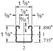
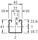
A 1-5/8″ x 1-5/8″ channel, the Unistrut P2000 is similar in size to the P1000 but with a 16 ga (.060″) wall.
| Elements of Section – P2000 | ||
| Area of Section | 0.342 in2 (2.2 cm2) | |
| Axis 1-1 | Axis 2-2 | |
| Moment of Inertia (I) | 0.125 in4 (5.2 cm4) | 0.151 in4 (6.3 cm4) |
| Section Modulus (S) | 0.140 in3 (2.3 cm3) | 0.186 in3 (3.0 cm3) |
| Radius of Gyration (r) | 0.604 in(1.5 cm) | 0.665 in(1.7 cm) |
| Column Loading – P2000 Unbraced Height (in) Allowable Load at Slot Face (lbs) Max Column Load Applied at C.G. K=0.65 (lbs) K=0.80 (lbs) K=1.0 (lbs) K=1.2 (lbs) 24 2,400 6,650 6,080 5,280 4,470 36 2,050 5,380 4,470 3,370 2,500 48 1,600 4,090 3,040 2,100 1,590 60 1,230 2,960 2,100 1,500 1,160 72 970 2,190 1,590 1,160 910 84 790 1,720 1,270 950 760 96 660 1,410 1,060 800 650 108 570 1,200 910 700 * 120 510 1,040 800 620 * 144 420 830 650 * * *KL/r > 200 |
| Beam Loading – P2000 | ||||||
| Span (in) | Max Allowable Uniform Load (lbs) | Defl at Uniform load (in) | Uniform Loading at Deflection | Lateral Bracing Reduction Factor | ||
| Span /180 (lbs) | Span /240 (lbs) | Span /360 (lbs) | ||||
| 24 | 1,170 | 0.06 | 1,170 | 1,170 | 1,170 | 1.00 |
| 36 | 780 | 0.13 | 780 | 780 | 610 | 0.88 |
| 48 | 590 | 0.23 | 590 | 510 | 340 | 0.75 |
| 60 | 470 | 0.36 | 440 | 330 | 220 | 0.61 |
| 72 | 390 | 0.52 | 300 | 230 | 150 | 0.48 |
| 84 | 340 | 0.71 | 220 | 170 | 110 | 0.41 |
| 96 | 290 | 0.91 | 170 | 130 | 90 | 0.35 |
| 108 | 260 | 1.16 | 130 | 100 | 70 | 0.32 |
| 120 | 230 | 1.41 | 110 | 80 | 50 | 0.29 |
| 144 | 200 | 2.12 | 80 | 60 | 40 | 0.25 |
| 168 | 170 | 2.86 | 60 | 40 | 30 | 0.23 |
| 192 | 150 | 3.76 | 40 | 30 | 20 | 0.21 |
| 216 | 130 | 4.64 | 30 | 30 | – | 0.19 |
| 240 | 120 | 5.88 | 30 | – | – | 0.18 |
Notes:
- Above loads include the weight of the member. This weight must be deducted to arrive at the net allowable load the beam will support.
- Long span beams should be supported so as to prevent rotation and twist.
- Allowable uniformly distributed loads are listed for various simple spans, that is, a beam on two supports. If load is concentrated at the center of the span, multiply load from the table by 0.5 and corresponding deflection by 0.8.
- The lateral bracing factor should be multiplied by the load to determine the load retained based on the distance between lateral braces.