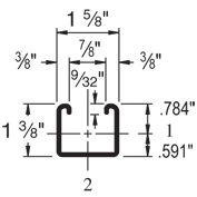
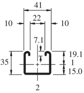
The Unistrut P3000 is a 1-5/8″ x 1-3/8″ channel. It is slightly shorter than the P1000 and has a 12 ga (.105″) wall.
| Elements of Section – P3000 | ||
| Area of Section | 0.500 in2 (3.2 cm2) | |
| Axis 1-1 | Axis 2-2 | |
| Moment of Inertia (I) | 0.120 in4 (5.0 cm4) | 0.203 in4 (8.4 cm4) |
| Section Modulus (S) | 0.153 in3 (2.5 cm3) | 0.250 in3 (4.1 cm3) |
| Radius of Gyration (r) | 0.489 in(1.2 cm) | 0.638 in(1.6 cm) |
| Column Loading – P3000 Unbraced Height (in) Allowable Load at Slot Face (lbs) Max Column Load Applied at C.G. K=0.65 (lbs) K=0.80 (lbs) K=1.0 (lbs) K=1.2 (lbs) 24 3,180 9,690 8,980 8,050 7,210 36 2,920 8,160 7,210 6,130 5,240 48 2,590 6,820 5,810 4,730 3,860 60 2,300 5,740 4,730 3,690 2,990 72 2,040 4,850 3,860 2,990 2,270 84 1,830 4,100 3,240 2,400 * 96 1,650 3,530 2,770 1,840 * 108 1,450 3,080 2,270 * * 120 1,250 2,710 1,840 * * *KL/r > 200 |
| Beam Loading – P3000 | ||||||
| Span (in) | Max Allowable Uniform Load (lbs) | Defl at Uniform load (in) | Uniform Loading at Deflection | Lateral Bracing Reduction Factor | ||
| Span /180 (lbs) | Span /240 (lbs) | Span /360 (lbs) | ||||
| 24 | 1,280 | 0.07 | 1,280 | 1,280 | 1,280 | 1.00 |
| 36 | 850 | 0.15 | 850 | 850 | 580 | 0.96 |
| 48 | 640 | 0.26 | 640 | 490 | 330 | 0.91 |
| 60 | 510 | 0.41 | 420 | 310 | 210 | 0.88 |
| 72 | 430 | 0.59 | 290 | 220 | 150 | 0.84 |
| 84 | 370 | 0.81 | 210 | 160 | 110 | 0.82 |
| 96 | 320 | 1.05 | 160 | 120 | 80 | 0.79 |
| 108 | 280 | 1.30 | 130 | 100 | 60 | 0.77 |
| 120 | 260 | 1.66 | 100 | 80 | 50 | 0.75 |
| 144 | 210 | 2.32 | 70 | 50 | 40 | 0.70 |
| 168 | 180 | 3.15 | 50 | 40 | 30 | 0.66 |
| 192 | 160 | 4.18 | 40 | 30 | – | 0.62 |
| 216 | 140 | 5.21 | – | – | – | 0.58 |
| 240 | 130 | 6.64 | – | – | – | 0.54 |
Notes:
- Above loads include the weight of the member. This weight must be deducted to arrive at the net allowable load the beam will support.
- Long span beams should be supported so as to prevent rotation and twist.
- Allowable uniformly distributed loads are listed for various simple spans, that is, a beam on two supports. If load is concentrated at the center of the span, multiply load from the table by 0.5 and corresponding deflection by 0.8.
- The lateral bracing factor should be multiplied by the load to determine the load retained based on the distance between lateral braces.