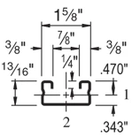
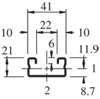
The P4000 is a 1-5/8″ x 13/16″ Unistrut channel with a 16 ga (.060″) wall. It is slightly shorter than the P3300.
| Elements of Section – P4000 | ||
| Area of Section | 0.244 in2 (1.6 cm2) | |
| Axis 1-1 | Axis 2-2 | |
| Moment of Inertia (I) | 0.023 in4 (1.0 cm4) | 0.092 in4 (3.8 cm4) |
| Section Modulus (S) | 0.049 in3 (0.8 cm3) | 0.113 in3 (1.9 cm3) |
| Radius of Gyration (r) | 0.306 in(0.8 cm) | 0.613 in(1.6 cm) |
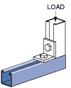
| Column Loading – P4000 Unbraced Height (in) Allowable Load at Slot Face (lbs) Max Column Load Applied at C.G. K=0.65 (lbs) K=0.80 (lbs) K=1.0 (lbs) K=1.2 (lbs) 24 1,630 4,670 4,290 3,780 3,310 36 1,450 3,840 3,310 2,460 1,730 48 1,160 3,030 2,190 1,400 970 60 870 2,120 1,400 900 * 72 670 1,470 970 * * *KL/r > 200 |
| Beam Loading – P4000 | ||||||
| Span (in) | Max Allowable Uniform Load (lbs) | Defl at Uniform load (in) | Uniform Loading at Deflection | Lateral Bracing Reduction Factor | ||
| Span /180 (lbs) | Span /240 (lbs) | Span /360 (lbs) | ||||
| 24 | 410 | 0.11 | 410 | 370 | 250 | 1.00 |
| 36 | 270 | 0.24 | 220 | 170 | 110 | 0.94 |
| 48 | 200 | 0.43 | 120 | 90 | 60 | 0.88 |
| 60 | 160 | 0.67 | 80 | 60 | 40 | 0.83 |
| 72 | 140 | 1.01 | 60 | 40 | 30 | 0.79 |
| 84 | 120 | 1.38 | 40 | 30 | 20 | 0.75 |
| 96 | 100 | 1.72 | 30 | 20 | 20 | 0.72 |
| 108 | 90 | 2.20 | 20 | 20 | 10 | 0.69 |
| 120 | 80 | 2.68 | 20 | 10 | 10 | 0.66 |
Notes:
- Above loads include the weight of the member. This weight must be deducted to arrive at the net allowable load the beam will support.
- Long span beams should be supported so as to prevent rotation and twist.
- Allowable uniformly distributed loads are listed for various simple spans, that is, a beam on two supports. If load is concentrated at the center of the span, multiply load from the table by 0.5 and corresponding deflection by 0.8.
- The lateral bracing factor should be multiplied by the load to determine the load retained based on the distance between lateral braces.
| Part No. | Finish | Length | Weight | Box Qty. |
| P4000 | GR | 20 | 83.00 | 1000 |
| P4000 | GR | 10 | 83.00 | 500 |
| P4000 | PG | 20 | 82.00 | 1000 |
| P4000 | PG | 10 | 82.00 | 500 |
| P4000 | HG | 10 | 86.90 | 500 |
| P4000 | HG | 20 | 86.90 | 1000 |
| P4000 | ZD | 20 | 82.00 | 1000 |
| P4000 | ZD | 10 | 82.00 | 500 |
| P4000 | PL | 20 | 82.00 | 1000 |
| P4000 | PL | 10 | 82.00 | 500 |
| P4000 | EA | 20 | 45.00 | 1000 |
| P4000 | EA | 10 | 45.00 | 500 |
| P4000 | SS | 10 | 82.00 | 500 |
| P4000 | SS | 20 | 82.00 | 1000 |
| P4000 | ST | 20 | 82.00 | 1000 |
| P4000 | ST | 10 | 82.00 | 500 |