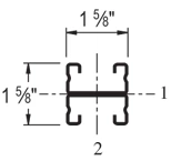
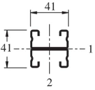
The Unistrut P4100 channel has dimensions of 1-5/8″ x 13/16″ and a 14 ga (.075″) wall. It is slightly shorter than the P3300.
| Elements of Section – P4100 | ||
| Area of Section | 0.290 in2 (1.9 cm2) | |
| Axis 1-1 | Axis 2-2 | |
| Moment of Inertia (I) | 0.026 in4 (1.1 cm4) | 0.107 in4 (4.5 cm4) |
| Section Modulus (S) | 0.054 in3 (0.9 cm3) | 0.132 in3 (2.2 cm3) |
| Radius of Gyration (r) | 0.298 in(0.8 cm) | 0.609 in(1.5 cm) |
| Column Loading – P4100 Unbraced Height (in) Allowable Load at Slot Face (lbs) Max Column Load Applied at C.G. K=0.65 (lbs) K=0.80 (lbs) K=1.0 (lbs) K=1.2 (lbs) 24 1,840 5,610 5,210 4,570 3,850 36 1,640 4,660 3,850 2,800 1,960 48 1,310 3,490 2,480 1,590 1,100 60 1,000 2,400 1,590 * * 72 770 1,670 1,100 * * *KL/r > 200 |
| Beam Loading – P4100 | ||||||
| Span (in) | Max Allowable Uniform Load (lbs) | Defl at Uniform load (in) | Uniform Loading at Deflection | Lateral Bracing Reduction Factor | ||
| Span /180 (lbs) | Span /240 (lbs) | Span /360 (lbs) | ||||
| 24 | 450 | 0.11 | 450 | 420 | 280 | 1.00 |
| 36 | 300 | 0.24 | 250 | 190 | 130 | 0.98 |
| 48 | 230 | 0.44 | 140 | 110 | 70 | 0.94 |
| 60 | 180 | 0.67 | 90 | 70 | 50 | 0.91 |
| 72 | 150 | 0.96 | 60 | 50 | 30 | 0.89 |
| 84 | 130 | 1.32 | 50 | 30 | 20 | 0.86 |
| 96 | 110 | 1.67 | 40 | 30 | 20 | 0.84 |
| 108 | 100 | 2.16 | 30 | 20 | 10 | 0.82 |
| 120 | 90 | 2.67 | 20 | 20 | 10 | 0.80 |
| 144 | 80 | 4.09 | 20 | – | – | 0.76 |
| 168 | 60 | 4.88 | – | – | – | 0.73 |
| 192 | 60 | 7.28 | – | – | – | 0.69 |
| 216 | 50 | 8.64 | – | – | – | 0.65 |
| 240 | 50 | 11.85 | – | – | – | 0.61 |
Notes:
- Above loads include the weight of the member. This weight must be deducted to arrive at the net allowable load the beam will support.
- Long span beams should be supported so as to prevent rotation and twist.
- Allowable uniformly distributed loads are listed for various simple spans, that is, a beam on two supports. If load is concentrated at the center of the span, multiply load from the table by 0.5 and corresponding deflection by 0.8.
- The lateral bracing factor should be multiplied by the load to determine the load retained based on the distance between lateral braces.