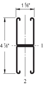
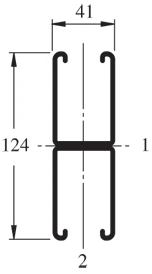
The Unistrut P5501 is a 1-5/8″ x 4-7/8″ back-to-back channel. It has a 12 ga (.105″) wall and is shorter than P5001 but taller than the P1001.
| Elements of Section – P5501 | ||
| Area of Section | 1.452 in2 (9.4 cm2) | |
| Axis 1-1 | Axis 2-2 | |
| Moment of Inertia (I) | 2.805 in4 (116.8 cm4) | 0.669 in4 (27.8 cm4) |
| Section Modulus (S) | 1.151 in3 (18.9 cm3) | 0.823 in3 (13.5 cm3) |
| Radius of Gyration (r) | 1.390 in(3.5 cm) | 0.679 in(1.7 cm) |
| Column Loading – P5501 Unbraced Height (in) Allowable Load at Slot Face (lbs) Max Column Load Applied at C.G. K=0.65 (lbs) K=0.80 (lbs) K=1.0 (lbs) K=1.2 (lbs) 24 8,580 31,810 30,880 29,520 28,100 36 8,350 29,700 28,100 26,000 24,070 48 8,080 27,390 25,330 22,910 20,940 60 7,720 25,170 22,910 20,510 17,170 72 7,270 23,190 20,940 17,170 12,700 84 6,780 21,510 18,740 13,430 9,330 96 6,130 20,110 15,630 10,290 7,150 108 5,450 17,750 12,700 8,130 5,650 120 4,800 15,260 10,290 6,590 * 144 3,760 10,830 7,150 * * 168 2,970 7,950 5,250 * * *KL/r > 200 |
| Beam Loading – P5501 | ||||||
| Span (in) | Max Allowable Uniform Load (lbs) | Defl at Uniform load (in) | Uniform Loading at Deflection | Lateral Bracing Reduction Factor | ||
| Span /180 (lbs) | Span /240 (lbs) | Span /360 (lbs) | ||||
| 24 | *5,220 | 0.01 | *5,220 | *5,220 | *5,220 | 1.00 |
| 36 | *5,220 | 0.04 | *5,220 | *5,220 | *5,220 | 1.00 |
| 48 | 4,820 | 0.08 | 4,820 | 4,820 | 4,820 | 0.98 |
| 60 | 3,860 | 0.13 | 3,860 | 3,860 | 3,860 | 0.93 |
| 72 | 3,220 | 0.19 | 3,220 | 3,220 | 3,220 | 0.87 |
| 84 | 2,760 | 0.26 | 2,760 | 2,760 | 2,500 | 0.81 |
| 96 | 2,410 | 0.34 | 2,410 | 2,410 | 1,920 | 0.76 |
| 108 | 2,140 | 0.42 | 2,140 | 2,140 | 1,510 | 0.70 |
| 120 | 1,930 | 0.52 | 1,930 | 1,840 | 1,230 | 0.64 |
| 144 | 1,610 | 0.76 | 1,610 | 1,280 | 850 | 0.53 |
| 168 | 1,380 | 1.03 | 1,250 | 940 | 630 | 0.45 |
| 192 | 1,210 | 1.35 | 960 | 720 | 480 | 0.39 |
| 216 | 1,070 | 1.70 | 760 | 570 | 380 | 0.34 |
| 240 | 960 | 2.09 | 610 | 460 | 310 | 0.30 |
| *Load limited by weld shear | ||||||
Notes:
- Above loads include the weight of the member. This weight must be deducted to arrive at the net allowable load the beam will support.
- Long span beams should be supported so as to prevent rotation and twist.
- Allowable uniformly distributed loads are listed for various simple spans, that is, a beam on two supports. If load is concentrated at the center of the span, multiply load from the table by 0.5 and corresponding deflection by 0.8.
- The lateral bracing factor should be multiplied by the load to determine the load retained based on the distance between lateral braces.