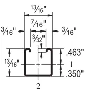
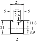
| Elements of Section – P6000 | ||
| Area of Section | 0.107 in2 (0.7 cm2) | |
| Axis 1-1 | Axis 2-2 | |
| Moment of Inertia (I) | 0.009 in4 (0.4 cm4) | 0.012 in4 (0.5 cm4) |
| Section Modulus (S) | 0.020 in3 (0.3 cm3) | 0.029 in3 (0.5 cm3) |
| Radius of Gyration (r) | 0.295 in (0.7 cm ) | 0.333 in (0.8 cm ) |
| Column Loading – P6000Unbraced Height (in)Allowable Load at Slot Face (lbs)Max Column Load Applied at C.G.K=0.65 (lbs)K=0.80 (lbs)K=1.0 (lbs)K=1.2 (lbs)186001,6601,4001,100860244901,3001,0107405903042099074056045036340770590450370423006304903803104826054042033027054240470370290*60210410330**66210370300**72180340270***KL/r > 200 |
| Beam Loading – P6000 | ||||||
| Span (in) | Max Allowable Uniform Load (lbs) | Defl at Uniform load (in) | Uniform Loading at Deflection | Lateral Bracing Reduction Factor | ||
| Span /180 (lbs) | Span /240 (lbs) | Span /360 (lbs) | ||||
| 18 | 230 | 0.06 | 230 | 230 | 180 | 0.90 |
| 24 | 170 | 0.11 | 170 | 150 | 100 | 0.80 |
| 30 | 140 | 0.18 | 130 | 100 | 70 | 0.80 |
| 36 | 110 | 0.24 | 90 | 70 | 50 | 0.63 |
| 42 | 100 | 0.35 | 70 | 50 | 30 | 0.63 |
| 48 | 80 | 0.42 | 50 | 40 | 30 | 0.52 |
| 54 | 80 | 0.60 | 40 | 30 | 20 | 0.52 |
| 60 | 70 | 0.72 | 30 | 20 | 20 | 0.45 |
| 66 | 60 | 0.82 | 30 | 20 | 10 | 0.45 |
| 72 | 60 | 1.06 | 20 | 20 | 10 | 0.40 |
Notes:
- Above loads include the weight of the member. This weight must be deducted to arrive at the net allowable load the beam will support.
- Long span beams should be supported so as to prevent rotation and twist.
- Allowable uniformly distributed loads are listed for various simple spans, that is, a beam on two supports. If load is concentrated at the center of the span, multiply load from the table by 0.5 and corresponding deflection by 0.8.
- The lateral bracing factor should be multiplied by the load to determine the load retained based on the distance between lateral braces.