| Elements of Section – P6001 | ||
| Area of Section | 0.213 in2 (1.4 cm2) | |
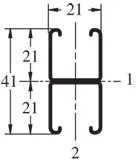
| Axis 1-1 | Axis 2-2 | |
| Moment of Inertia (I) | 0.045 in4 (1.9 cm4) | 0.024 in4 (1.0 cm4) |
| Section Modulus (S) | 0.055 in3 (0.9 cm3) | 0.058 in3 (1.0 cm3) |
| Radius of Gyration (r) | 0.460 in (1.2 cm ) | 0.333 in (0.8 cm ) |
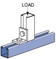
| Column Loading – P6001Unbraced Height (in)Allowable Load at Slot Face (lbs)Max Column Load Applied at C.G.K=0.65 (lbs)K=0.80 (lbs)K=1.0 (lbs)K=1.2 (lbs)181,2104,3204,0803,7703,500241,1703,9803,6803,3303,060301,1303,6503,3303,0002,460361,0703,3703,0602,4601,800421,0203,1402,6901,9001,320489002,9302,2301,4601,010548202,5501,8001,150800607002,1801,460930*667001,8301,210770*725501,5301,010***KL/r > 200 |
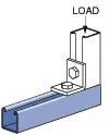
| Beam Loading – P6001 | ||||||
| Span (in) | Max Allowable Uniform Load (lbs) | Defl at Uniform load (in) | Uniform Loading at Deflection | Lateral Bracing Reduction Factor | ||
| Span /180 (lbs) | Span /240 (lbs) | Span /360 (lbs) | ||||
| 18 | 620 | 0.04 | 620 | 620 | 620 | 1.00 |
| 24 | 460 | 0.06 | 460 | 460 | 460 | 0.99 |
| 30 | 370 | 0.10 | 370 | 370 | 320 | 0.99 |
| 36 | 310 | 0.14 | 310 | 310 | 220 | 0.89 |
| 42 | 270 | 0.20 | 270 | 240 | 160 | 0.89 |
| 48 | 230 | 0.25 | 230 | 180 | 120 | 0.79 |
| 54 | 210 | 0.32 | 190 | 150 | 100 | 0.79 |
| 60 | 190 | 0.40 | 160 | 120 | 80 | 0.70 |
| 66 | 170 | 0.48 | 130 | 100 | 70 | 0.70 |
| 72 | 150 | 0.55 | 110 | 80 | 50 | 0.60 |
Notes:
- Above loads include the weight of the member. This weight must be deducted to arrive at the net allowable load the beam will support.
- Long span beams should be supported so as to prevent rotation and twist.
- Allowable uniformly distributed loads are listed for various simple spans, that is, a beam on two supports. If load is concentrated at the center of the span, multiply load from the table by 0.5 and corresponding deflection by 0.8.
- The lateral bracing factor should be multiplied by the load to determine the load retained based on the distance between lateral braces.