| Elements of Section – P7000 | ||
| Area of Section | 0.074 in2 (0.5 cm2) | |
| Axis 1-1 | Axis 2-2 | |
| Moment of Inertia (I) | 0.002 in4 (0.1 cm4) | 0.007 in4 (0.3 cm4) |
| Section Modulus (S) | 0.007 in3 (0.1 cm3) | 0.017 in3 (0.3 cm3) |
| Radius of Gyration (r) | 0.150 in (0.4 cm ) | 0.307 in (0.8 cm ) |
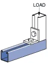
| Column Loading – P7000Unbraced Height (in)Allowable Load at Slot Face (lbs)Max Column Load Applied at C.G.K=0.65 (lbs)K=0.80 (lbs)K=1.0 (lbs)K=1.2 (lbs)184201,2009907205102433090064041028030260620410**36200430280***KL/r > 200 |
| Beam Loading – P7000 | ||||||
| Span (in) | Max Allowable Uniform Load (lbs) | Defl at Uniform load (in) | Uniform Loading at Deflection | Lateral Bracing Reduction Factor | ||
| Span /180 (lbs) | Span /240 (lbs) | Span /360 (lbs) | ||||
| 18 | 80 | 0.12 | 60 | 50 | 30 | 0.98 |
| 24 | 60 | 0.22 | 40 | 30 | 20 | 0.95 |
| 30 | 50 | 0.36 | 20 | 20 | 10 | 0.95 |
| 36 | 40 | 0.50 | 20 | 10 | 10 | 0.90 |
Notes:
- Above loads include the weight of the member. This weight must be deducted to arrive at the net allowable load the beam will support.
- Long span beams should be supported so as to prevent rotation and twist.
- Allowable uniformly distributed loads are listed for various simple spans, that is, a beam on two supports. If load is concentrated at the center of the span, multiply load from the table by 0.5 and corresponding deflection by 0.8.
- The lateral bracing factor should be multiplied by the load to determine the load retained based on the distance between lateral braces.